


Subject purpose:
This tutorial is about the use of an Arduino microcontroller with the STONE display. Arduino beginner tutorial, Arduino entry-level tutorial.
Hope to achieve: the more detailed the better, so that most of the small partners who do not understand the STONE serial screen products and the Arduino microcontroller can follow the steps can operate the kind of detailed description. Every step is clear. How to download and what to do next. Follow the instructions in this tutorial, but my code in, and restore the project to the kind that works.
There are a lot of Arduino tutorials online that fail…… There are plenty of examples available on GitHub. The first step stumbles most beginners.
Therefore, this time to “point-and-shoot camera” recording. Some engineers “warrior” said that (Arduino) children just play, let him use Arduino to do projects, is to insult his personality, haha…… This article entry-level is not aimed at these “warriors” write oh!
Hardware preparation:
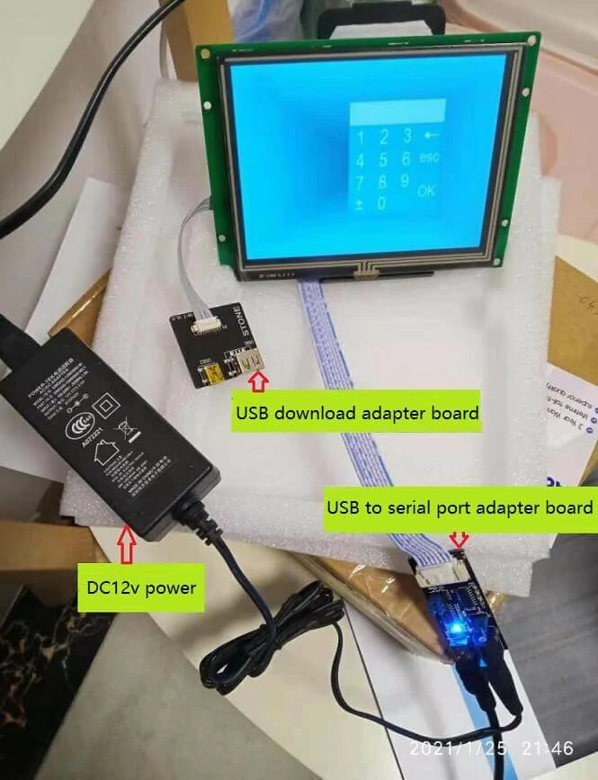
Serial port touch screen STVI056WT-01. With USB to serial port conversion board, USB download conversion board, supporting the connection cable, as shown in Figure 1.
Adapted DC12V power supply. You can go to the electronics city to buy it, or you can use the power supply of the TV set-top box at home to confirm the voltage and current (preferably 2A). You can plug in the USB to the serial port conversion board, as shown in Figure 1.
Red Arduino development board. The model is LY-F2 of Seven Star Bug, which comes with a USB cable for the power supply. As shown in figure 2.
electric iron. When buying an Arduino development board, remember to provide some connecting wires. TX and RX lines of serial ports should be connected, and GND should be welded. As shown in figure 2.
commonly used DC5V power supply. This will be available because you can use the charger, mobile phone charger, computer USB charging socket oh.
Tutorial Directory:
1. Hardware connection
Connect the Stone screen, USB to serial port conversion board, USB download conversion board;
Connect USB to the serial port conversion board and Arduino development board communication line;
Connect DC12V and DC5V power supply;
2. Software installation
Installation of STONE serial port screen related software;
Installation of Arduino development board software;
3. How to make both the screen and the Arduino move?
Make the STONE serial port screen move;
Get the Arduino development board moving;
Let Stone serial port touch screen and Arduino development board communicate and interact.
Next, document the process.
I. Hardware connection.
A. Connect the Stone screen, USB to serial port conversion board, USB download conversion board
Connection Instructions: USB to Serial Switch Board is the longboard with DC12V power socket JP1 on it. The STVI056WT-01 serial port touch screen is used. The two cables in Figure 1 are provided by the government. The socket behind the screen is also “anti-stupid”.
The conversion board from USB to serial port needs to be connected to the DC12V power supply, which is not allocated by the government. You need to buy it by yourself. The core wire is positive! My own DC12V power supply is a 2A current, ready-made TV set-top box power supply at home, the effect is very good.
 Figure 1 :(real shot of connecting Stone screen, USB to serial port conversion board, USB download conversion board)
B. Connect the USB communication line to the serial port conversion board and the Arduino development board
You can take off the USB to serial port conversion board near the row of a jumper, with 3 lines (need to move the electric iron, because the USB to serial port conversion board does not have GND lead point —– hope that the official STONE can improve it, it is best to also give 3 serial port connection line, now we can only go to find.
I’m ok, there is inventory, and the advanced “silly white sweet” may be embarrassed oh, it is better to buy an Arduino development board with some!) Figure 2 Connection. The black GND line is soldered firmly along with the soldering pad of the USB socket with an electric soldering iron, and the second hole at the position shown in the illustration on the other end (the corresponding hole position on the board is marked with GND); The green and blue lines should be inserted correctly, not backward. The USB to serial port conversion board is shown in Figure 2. The blue line is connected to the upper right pin and the green line to the lower left pin (the jumper short connection here has been removed!). The red Arduino development board, the model of which is Ly-F2 of Seven Star Bug, is shown here as shown in Figure 2. The green is R0X and the blue is TX, which should be marked.
Aggressive “silly white sweet” people, come on!
 Figure 2 :(Real shot of connecting USB to serial port conversion board and Arduino development board)
C. Connect DC12V and DC5V power supply
The USB to serial port conversion board is equipped with an official USB cable. The Arduino development board is also equipped with a USB cable when purchased. The DC12V power supply is its own, so it can be connected as shown in Figure 3. My own DC12V power is plugged directly into an AC220V socket, and the two USB cables delivered require a DC5V converter, which works with most phone chargers. So, this step is not difficult (should have 2 mobile phone chargers, or charge treasure always should have, haha…… You can also plug in a USB port on your computer that charges your phone!)
.webp "Arduino Tutorial for Beginners LY-F2 of Seven Star Bug +STONE Serial Screen")